What it solves and why you would use it
A coordination model needs repeatable floor and zone packages. This tool builds the level × scope-box combinations, applies a common template and browser parameter, and can update the same views after a model revision.
Before you start
Install the plug-in for your version of Revit and open a sample model.
A three-level model with two scope boxes and an existing 3D coordination template.
Open the tool: EZ VDC > Coordination > 3D View Creator; verify the exact ribbon caption in the installed build.
Worked workflows
Example: floor-by-zone coordination package
- Choose the linked architectural model as the level source and select Levels 01–03.
- Select the host scope boxes East and West. Set the bottom offset to include the slab and use a suitable top offset.
- Use 3D_{Scope}_{Level}, choose a coordination template and set the browser-group value.
- Enable NWC export only if required; choose the folder and linked-model option.
- Create views, review the six planned names and confirm. Re-run with Update existing after the next revision.
Expected result: Six floor/zone views when all three levels are eligible; matching views can be refreshed without renaming the package.
Every button and parameter
Open a window or tab below to find its controls. Interface names match the plug-in; you can also search by function or unit.
16 of 16 reference entries
Choose the model and slices
6 entries
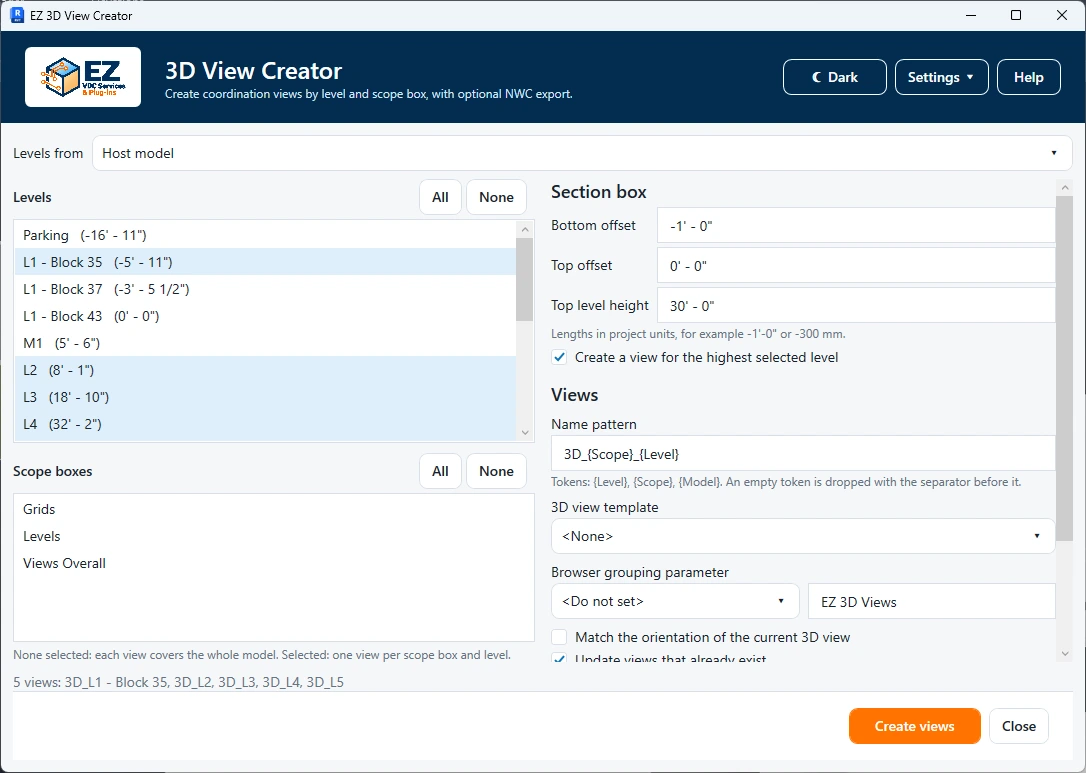
Levels can come from the host or a loaded link. Scope boxes belong to the current project. Read the selected names before creating the combinations.
- Level source
- Choose the model containing the levels. Use a linked architectural model when the coordination host has no useful levels; the chosen link instance supplies its placement transform.
- Levels · All / None
- Check the levels to include. All checks every level; None clears the list. At least one level is required. The highest-level option determines whether the last slice is generated.
- Scope boxes · All / None
- Check the host scope boxes that define the horizontal limits. Each checked box generates a view for each eligible level. All selects all boxes; None uses the unscoped model extent instead of a zone box.
- Bottom offset
- Length in project units, added to the current level. A negative value extends below the level to include its slab. The initial default is −1 ft, displayed in the project’s units.
- Top offset
- Length added to the level above the slice; initially zero. For example, a negative offset stops below the next level. The resulting top must remain above the bottom.
- Highest selected level · Include / Height
- Include enables the last slice, which has no selected level above it. Height supplies its vertical extent; initially 30 ft in project units. With only one selected level, include it to obtain a view.
Naming, appearance and repeat runs
5 entries
Names must be valid and unique across all planned views. Saved settings are a starting point: check them when switching projects.
- View name pattern
- Use {Level}, {Scope} and {Model}; tokens are case-insensitive. The default is 3D_{Scope}_{Level}. When no scope exists, its empty token and adjacent separators are cleaned. Inspect the planned names for collisions.
- View template
- Choose a 3D view template or <None>. The template controls display and any parameters it locks; use a coordination template that exposes the geometry needed for export.
- Browser grouping · Parameter / Text value / Valid choice
- Select a supported writable view parameter, or Do not set. Text uses the value field, initially EZ3DViews. Discipline and Phase use their valid dropdown choices instead; choose one before creation. The selected value is written to every generated view, so match your Browser Organization rules.
- Match current 3D orientation
- Available when the active view is a non-template 3D view. Copies that viewing direction to the generated views. Open the desired 3D view first if you want a consistent presentation angle.
- Update views that already exist
- Checked by default. A matching name updates the existing view instead of creating a second copy. Review the pattern before re-running because name matching determines which views are updated.
Export and create
5 entries
NWC export is optional and requires the Autodesk NWC exporter installed for the running Revit version.
- Export each view to NWC
- Exports one NWC per generated view using shared coordinates. If the exporter is unavailable, this option is disabled. View visibility and the template affect the exported content.
- Export folder · Browse
- Browse selects a writable destination; you can also enter its path. Verify the folder in the confirmation summary. Exported files are disk outputs and are separate from Revit’s model Undo.
- Include linked models in the NWC
- Checked initially. Include loaded linked geometry when the coordination package needs it; clear it for host-only exports.
- Create views
- Validates the levels, offsets, unique names and export setup, then presents a planned-view summary for confirmation. Confirm to create/update views and run enabled exports. Read the final created, updated, skipped and export results.
- Close
- Closes the configuration window without generating views.
Check the result
- Open a lower and the highest view: verify the bottom includes the intended slab, the top cut is correct and the chosen scope box encloses the expected zone.
- Confirm browser parameter values and exported NWC coordinates in your coordination model. A successful view creation does not establish that the exported model is aligned.
Troubleshooting and limits
- Duplicate planned names or a top below its bottom must be corrected before creation. Choose a loaded level source and install the matching NWC exporter if export is unavailable.
Running it again
Update views that already exist refreshes views with the target name instead of creating numbered copies.